Design Condenser TD Condensing Temp Ambient Temp 110 95 20 TD. Fin style0Straight 1Slot 2Triangle wave 3Sine wave Tube material-1See notes 0Copper 1Steel 2Aluminum.

Vacuum Systems Non Barometric Mixing Condensers Vacuum Ejector Korting Hannover Gmbh
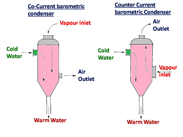
It is the simplest design of all barometric condensers and requires no auxiliary air pump or precooler.

. Innovative evaporatively cooled condensers with conventional air cooled condenser for a split heat pump system. Specifying Steam Surface Condensers. Work out where the theoretical liquid level is in the leg then allow about an extra metre below that for.
Calculate the length of the tube or heat exchanger. Condenser Design has had 1 update within the past 6 months. It is a measure of efficiency of condenser operation.
Note that this is the minimum barometric leg height. Duty Area Number of tubes ShellTube velocities flooding velocity and operating velocity for reflux condenser Reynolds numbers Condensation heat transfer coefficient Condensation flow regime Number of Baffles and Baffle spacing Scale resistance dirt factor Overall heat. OBJECTIVES equation Design of Air cooled condenser to avoid the wastage of Cmin is given by Wmk.
Circuits numberNB flow per circuit. As 1 of Hg equals 1133 feet of water a minimum barometric leg of 295 feet is required. This Multimedia Edition contains interactive features that bring the rigorous and authoritative material from HEDH to life.
The Barometric condenser will perform the VLE calculations on the species specified by the user in the VLE block. DESIGN CALCULATIONS FOR CONDENSER Inlet temperature of the process stream T1 45 o C Outlet temperature of the process stream T2 45 o C Inlet temperature of the water t1 25 0 C Outlet temperature of the water t2 40 o C Mass flow rate of the process stream m 8060 Kghr Enthalpy of Vapors of Process Stream 1940 KJKg. Up to 24 cash back Detailed calculation than displays many calculated variables such as.
Condenser efficiency T2 - T1 X 100 T3 - T1 T2. The simplest design of all barometric condensers and requires no auxiliary air pump or pre-cooler. The Sugar Engineers condenser design is the of the rain-tray type.
These capacities are given in MBHTD. The condenser is generally employed where low cost water is available in ample quantity. Its normally recommended that a 34 foot barometric leg be provided which allows the system to pull a pure vacuum and still allows the water and condensate to drain freely.
Katmar Chemical 20 May 13 0248. N X A X V Length of the tubes required 166624. Modeling the performance characteristics of water-cooled Air-conditioners 9.
Multimedia Edition of Heat Exchanger Design Handbook HEDH is the standard reference source for heat transfer and heat exchanger design. Water The heat transfer in tube is given by effectiveness Calculation of pressure drop of tube side to evaluate the of heat exchangerCmin Ttubeinlet Tairinletlength of tube temperature at the outlet We get heat transfer in Wtube this. Condenser capacities for 60 Hz are located in Table 4.
GPM PPH x 1000 T 2-T 1500C p SG GPM gallons per minute of condensing fluid. Duty Area Number of tubes ShellTube velocities flooding velocity and operating velocity for reflux condenser Reynolds numbers Condensation heat transfer coefficient Condensation flow regime Number of Baffles and Baffle spacing Scale resistance dirt factor Overall heat transfer coefficient for. Condenser inlet cooling water temperature T3.
Initial condenser widthLD mm. H for condensers is often in between 75 to 1100 kcalhm 2 c 01 to 13 kWm 2 K. At the actual condenser pressure is known as the terminal difference.
After all the test it is found that evaporatively cooled condenser has higher capacity by 18 to 81 higher COP by 111 to 216 and higher SEER by 145. Online calculations for barometric condenser design. A typical air conditioning surface condenser specification is included.
Detailed calculation than displays many calculated variables such as. P Lt x Rt x R2 x R1 Re1Re2Re3 HEI for Surface Condenser-. S i i i row i T T T T E 1 _ s air in air out air in condenser T T T T E _ _ _ 1 where Ti is the air temperature upstream the i th row while T s is the condensation temperature.
Calculate Design Condenser TD. Temperature corresponding to the vacuum or absolute pressure in the condenser. Download Condenser Design for Windows to perform thermal design calculations for shell and tube condensers.
Factors affecting condenser design and selection. The lower part of the leg will be full of liquid and it could be run at a shallower angle than 45. Determine the amount of cooling water required in jet condenser to condense one kg vapour if cooling water inlet and outlet temperature is 20 0C and 30 0C respectively.
M 2556 1256 4187 58 kg. Condenser is also about 10F. Condenser outlet cooling water temperature T1.
Calculate the overall heat transfer coefficient. Calculate the capacity rate ratio. Calculate the heat transfer surface area.
H overall heat exchange coefficient kWm 2 K S area of the heat exchanger m 2 ΔT ml K The value of S can thus be calculated as a 1st approximation of the heat exchanger size. Thus the leaving water temperature approach is 20F125F minus 105F. A Pi X d X N X L Diameter of the condenser required 74749.
Convert the THR calculated in step 2 to MBHF TD by dividing by 1000 to get THR in MBH. Take heat of vapour H as 2556 kJkg at 30 0C and specific heat of cooling water as 4187 kJkg. The hotwell or in the condensing fluid outlet connection for the low level type barometric condenser.
This is normally H2O but it may be any species with VLE information in the Species Database eg. Parameters beginning from the calculation of the rows effectiveness and the condenser effectiveness as suggested by Fabbri 2. Cold injection water is conveyed by a central pipe up the length of the body to the rain tray.
The Multi-Jet Condenser is also used where the vacuum handled is not high and a moderately large terminal difference is permissible. Steps for design of heat exchanger Calculate the effectiveness. By Elliot Spencer Graham MfgCo Inc Great Neck Long Island NY.
The 45 angle limitation applies only to the two phase section. It is probably the ideal type where load conditions are constant and there is little air leakage. The temperature rise across the barometric is very helpful since it can aid in calculating the duty by the following formula.
DTube OD X sqrt no of tubes 027 Pressure drop across the condenser. Air inlet speed 0Ignore.

Barometric Condensers Schutte Koerting
Condenser System Vacuum Equipment In Sugar Single Entry Condenser

Barometric Jet Condenser Complete Explanation Youtube
Vacuum Systems Non Barometric Installation Surface Condenser Korting Hannover Gmbh
Jet Condenser Different Types Of Jet Condenser

Barometric Condensers Schutte Koerting

Barometric Condensers Schutte Koerting

Barometric Condensers Schutte Koerting
0 comments
Post a Comment